Many of us have modded the A4000 card with the Palit StormX or PNY 3060 coolers to make our own tiny "A4000 Aero" gpus.
The OC'd A4000 performs slightly better than the 3060 Ti, but draws much less power. It's power starved.
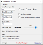
Shunt modding is the process of adding a resistor to the card in order to increase it's power draw. It was very popular with the A2000.
It's well known that the A4000 is power-limited 3070Ti card with a smaller PCB. Techspot does a great job breaking down the differences between them here.
Some relevant quotes ...
Does anyone have any ideas or suggestions on how to shunt mod the A4000? With the 8-pin power plug it may be possible to restore that 3070Ti performance and keep the 3060 Aero size.
I've seen a some whispers on reddit that it is possible, but I can't find any serious evidence that anyone has ever shunt modded the A4000.
Overclock crew, help me out. Do you think it's possible to shunt mod the A4000?
The OC'd A4000 performs slightly better than the 3060 Ti, but draws much less power. It's power starved.
Shunt modding is the process of adding a resistor to the card in order to increase it's power draw. It was very popular with the A2000.
Some relevant quotes ...
Previously, I didn't think shunt modding the the A4000 would do much because it only has a 6-pin PCIe plug, but youtuber Wiltshire Tutorials showed that the 8-pin traces on the A4000 are still active and you CAN solder on an 8-pin and it will work!
I've seen a some whispers on reddit that it is possible, but I can't find any serious evidence that anyone has ever shunt modded the A4000.
Overclock crew, help me out. Do you think it's possible to shunt mod the A4000?
")