Overclock.net banner

Progress on a fully custom mouse.

1 reading
76K views 186 replies 22 participants last post by  TranquilTempest  
#1 · (Edited)
Over the past few years I've slowly been gaining knowledge about electronics, and recently I've been thinking there's not really anything about mouse technology that really mystifies me, so why not try to design and build one myself? It might be a little overambitious, but there's nothing wrong with failing.


Details of the current design:
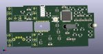
PMW3360 (3389 should be an easy change though)
8 hardware debounced switches, 3 of which will be on separate board, for thumb buttons.
ALPS encoder
MCU: EFM8UB10F16G-C-QFN28 (may change later, but want to at least try it first)
61mm x 60mm, but I think I can get it smaller.

Prototype shell will be made by vacuforming over a clay sculpture. If that doesn't work out I may try 3d printing.

This is the first PCB I've laid out, and I'm not quite done with it yet, but I think it's good enough to get some feedback on. Learning to use KiCAD at the same time:
 

Attachments

#4 ·
Partly trying to minimize size and deconflict buttons behind scroll wheel, partly because I vaguely remember a whitepaper from the era of ball mice about people being more accurate when the sensor was placed close to the index finger. Though I readily admit that study may have been based on people using a mouse for the first time ever, and I'm having a hard time finding it now.
 
#3 · (Edited)
The switches need 3 holes, your render at least to me has the middle leg blocked with some weird trace shapes. I don't get it either why mice sold in mass have no hardware debounce and instead rely on software with delays.

Never heard of that MCU, I would rather use some kind of AR but then I'm too lazy and cheap to go through all the trouble and expenses to make a custom mouse.

Good luck!


---

Why would sensor need to be centered on a PCB if it's centered on the mouse itself? ;)
There are some existing solutions for using 3360 with other MCUs dev boards. That's probably the trickiest part, to communicate with the sensor.
 
#5 ·
The switches need 3 holes, your render at least to me has the middle leg blocked with some weird trace shapes. I don't get it either why mice sold in mass have no hardware debounce and instead rely on software with delays.
That's just KiCAD being silly with the thermal relief on through hole ground pads, Those holes are indeed marked to be drilled. It's just showing up because it's not marked to be etched away.
Never heard of that MCU, I would rather use some kind of AR but then I'm too lazy and cheap to go through all the trouble and expenses to make a custom mouse.

Good luck!
ARM or AVR? The microcontroller choice is mostly me satisfying my own curiosity, though it is significantly cheaper than my second choice, which would be the atmega32u4.
---

Why would sensor need to be centered on a PCB if it's centered on the mouse itself? ;)
There are some existing solutions for using 3360 with other MCUs dev boards. That's probably the trickiest part, to communicate with the sensor.
Well, communicating with the sensor is just SPI, and there's a datasheet available, so not too big a deal.
 
#7 ·
I don't see any spi level converters. Are you going the voltage divider route, then running the mcu at 3.3v and hope the mcu sees the low voltage from the 3360? I once made a shell myself by using a blowlamp to melt perspex over another mouse, then a towel to press it down around it.
 
#8 · (Edited)
MCU has an internal 5v to 3.3v regulator, and that's what it runs its IO on. Said 3.3v also drives the sensor's VDDIO pin(internal regulator can provide up to 100mA). There is a separate 1.9v regulator for the sensor's normal VDD.

Might have picked a MCU that can run on 1.9 if USB signaling didn't need 3.3 anyway.

Interesting idea with molding a shell. I do have a heat gun that might work.
 
#16 · (Edited)
Not "official" ones, but I did make some.

The encoder footprint is a little sketchy. Couldn't figure out how to get routed slots in the footprint editor, so I used round holes. Maybe you can define plated slots somewhere else, but I haven't got that far yet. I believe pins 1 2 3 correspond to A B C, but you shouldn't trust me on that.

Switch footprint was much easier.
 

Attachments

#17 ·
Thanks for the help, I guess I can upload my schematic if I replace the proprietary sensor with an adns9800 or something, but it's nothing you haven't seen before. When I made my first pcb with fritzing I used 2mm holes for the sides of the ec10 encoder. I may have had to cut them down the side with a sidecutters, can't remember.

kicad only has ec11 mechanical encoders and from memory, those use the center pin as common, whereas the ec10 has an outer pin as common. I screwed up the first pcb I made, so after that I put an extra 2 mounting holes so that I could rotate the encoder 180 degrees to correct the wiring.

kicad still needs a little work, because the NO and NC pins are reversed between the spst and spdt.
 
#18 ·
I used 2.1mm holes because those pins have a kink in them, but I haven't tested if that's enough clearance or not. If it's not, I can just bend the pins straight to make it work.

And yeah, it would make more sense if pin 1 was common, pin 2 was NO, and pin 3 was NC. Though instead of messing with the existing symbol I just made the footprint match the symbol.
 
#19 ·
Good idea going for the 1.2mm hole for the microswitch pins. I used 1.25 which I found worked well. This pcb should be better than the old fritzing one because the bendpoints forced the middle click switch against the wheel. The pic is just a rough arrangement, nothing measured for the io1.1 yet. I don't think I can solder this smt mcu though. I'd love to use the alps em11b hall effect encoder, but if it is anything like the ec11 then it would hit the upper shell. maybe if it was countersunk into the wheel..
 

Attachments

#20 · (Edited)
That encoder would make the middle click a lot more complicated though. Maybe put it on a second PCB, so that it can move up and down with the mouse wheel.

As for soldering annoying surface mount parts, QFP isn't too bad, just drag a blob across the pins then wick up the excess. With the QFN I think I'm going to solder it before anything else, by tinning the pads first, using lots of flux, and reflowing the center pad by heating the bottom of the board with a heat gun.
 
#22 ·
Yup, at least for components with no pads in the middle. For QFN or BGA you need hot air.
practical question for you guys... where to obtain a 3360 sensor without desoldering? not sure if pixart provides samples or stuff. maybe jkicklighter might be willing to sell a sensor without his pcb.
There are a few sellers on aliexpress, but I don't know if any of them are official distributors.
 
#23 · (Edited)
I think the official european distributor is here https://www.codico.com/shop/en/pmk3360is-t2qu.html

have to buy a minimum of 5 but still not prohibitively expensive. I put off buying it until more is done, speed is not a priority.
I'll probably buy from aliexpress though, as it's just a one off, though I do have a tindie board which what appears to be a faulty sensor.

I screwed up a ps2 installing a mod chip, I just can't handle those ic packages, wish usb hid came in DIP packages, but I understand impedance would be off and weight would go up.
I was thinking of doing the em11b on flying leads like how the kone xtd encoder is done, except rather than use a cradle, solder a stiff copper wire between each mounting tab, then hinge the wire with vertical wire.

edit: here's where i'm at with the schematic.
 

Attachments

#24 ·
#25 ·
Update:

Lots of small changes. Got rid of a trace running under the SPI lines and two that were squeezing between the MCU and the sensor cutout. (got rid of the 1.9v enable, and decided to run the LED off the MCU instead of the 1.9v regulator).

Also got USB data lines to the top layer and ground either side.

Maybe an excessive amount of via stitching.

This is all probably completely unnecessary for a one off, but who knows, maybe if I end up selling these someday I'll have to comply with USB and FCC requirements.
 

Attachments

#26 ·
I received the sot-23 regulator the day after I ordered it, despite paying little for postage. tbh I regret buying those parts after I saw them, as I thought they were the largest, but soic is larger again. I think if you go for a custom mcu, you should go for an soic package, but that would be different for mass production.
 
#30 ·
Well, I've ordered my components. Waiting on the mouse wheel before I order the PCB, because I'll have to take some dimensions off of it. In theory everything should cost about $40~60, but with extras and tools I'm probably going to end up around $300 before I'm done.

Ordered sensors from China, two each of 3360 and 3389.
 
#31 ·
You're jumping in at the deep end, making a pcb without a working dev board prototype. It used to take 3 weeks for stuff to come from china, now it takes 3 months due to trade war or something. any idea as to why kicad won't let me attack a trace to the front of a via? back is no problem. the reason there's so many resistors is because I'm using 2 pullups per switch, and actually 4 pullups on the rotary encoder, because I wanted all the resistors to be the same size, so I seriesed some of them. resistors are sometimes handy for jumping traces anyway. I should probably have the decoupling caps closer.
For a production mouse i would prefer the ec11 to the ec10, no issue with shafts breaking or getting loose, plus you can get them in horizontal mount.
 

Attachments

#32 ·
Not sure about the via thing, the only issue I had with that was disconnecting part of a trace, reloading the netlist, then trying to reconnect to it. It could be a clearance issue. How are you placing the vias? I place mine by pressing v while drawing a trace.

As for jumping in at the deep end, Maybe a little bit, but I'm not too scared. I've looked at the code for the dev board's HID mouse demonstration, and the chip comes with a USB bootloader. skipping the dev board just changes the order in which I need to figure things out. Besides, getting a board made is cheaper than the dev board.
 
#33 ·
ah, the v trick worked out for me. must have been a bug of some kind. It would be cool if you could pull it off though. There are usb/ps2 keyboards which use v-usb on the atmega32a which is available in 40 pin dip, very easy to solder, and backwards compatible with ps2 ports (usb can't be bitbanged I understand). apparently the latency on the software usb isn't great though.
 
#34 ·
Got it routed after a struggle, I had to go back to the start and remove the led and extra level converter for motion, only 105 vias (ouch), 9 of those under the mcu, which all the sites warn not to do. who did you hire to make the pcb? I have a company lined up but they are pricy. now that i think of it I have to go back and thicken the traces for vcc and gnd.
 

Attachments

#36 · (Edited)
I've dealt with oshpark many times, helpful site. I guess maybe it is worth paying extra for it to be fully tested as I think they do. when i was using fritzing they were the only site that would accept my orders without errors. i thought kicad would give me more flexibility. customs here is a hassle buying from outside the eu but they don't think pcbs are expensive so i have got away with it so far. everything i buy is closely scrutinized though, has to be under 22 euro or so, or I get classed as a business and get a tax audit.

edit: ordered from jlcpcb 5 full size boards for 1.79 euro to my door. hard to believe.